This article was originally published on Med Device Online.
Prototyping parts for a novel product, or an existing product whose design is being updated, is a prudent practice. Prototypes can reduce overall development cost by mitigating design risk, and positively impact timelines by providing some insight into a part or protective solution’s utility and manufacturability.
However, debate often exists regarding the ideal type of prototype for a given project: specifically, whether to use 3D printing or injection molding to produce that prototype (or prototypes). Ultimately, there is no simple answer to this question. Several factors influence the decision, including the prototype’s purpose, timeline and cost concerns; part geometry; and the materials to be used for both prototyping and production.
In terms of initial timeline, 3D-printed parts generally hold a clear advantage. On average, once a design is submitted and printing begins, a 3D-printed prototype can be produced in as little as a few hours for small, simple geometries, or up to several days for larger, more complex pieces. The timeline also depends on the type of 3D printing used — for example, stereolithography (SLA), fused deposition modeling (FDM), selective laser sintering (SLS), digital light processing (DLP) or MultiJet Fusion (MJF) — and the material. More traditional prototypes produced using injection molding require tooling to create the mold, a process that can take anywhere from two to six weeks between drawing submission and part production.
Regarding cost, the per-part cost for molded prototypes can be as low as a few pennies, following capital investment in tooling and the mold. A 3D-printed part can cost anywhere from a few dollars to a few hundred dollars — again, depending on the part size, complexity and material. As prototype volume increases, though, so does the value of molding. For example, an organization that requires low-volume line trial testing (e.g., hundreds of pieces), or needs to test various iterations of the device into which the part will go, will find 3D printing prototypes quickly becomes both cost prohibitive and time consuming.
Another advantage of molded prototypes is the diversity of material representation. Consider that a 3D printer is limited by the materials and barometer ranges that can be printed. This is because only a few generic classes of material exist for 3D printing in some cases (e.g., a stiff material, a semi-flexible material, elastic, etc.), whereas a molded part may be composed of any 100+ different durometers (grades) of flexible thermoplastic elastomer (TPE) or low-density polyethylene (LDPE).
While these material limitations are more pronounced in SLA-type prints, FDM-type prints offer more flexibility. Still, not all materials will perform well in a 3D printer — even if they are, technically, printable. For example, an acrylonitrile butadiene styrene (ABS), PLA or a nylon generally will print well in an FDM printer. Polyethylene/polypropylene filament, meanwhile, can be produced in an FDM but the result is likely to be marred by warpage and other printing difficulties.
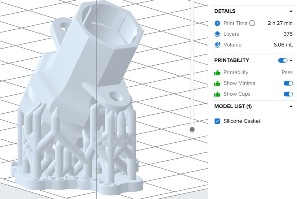
Fig. 1: With 3D printing, it’s possible to create complex geometries, but the process may require many layers, hours of print time and significant post-print cleanup work.
Consider that it is common risk-aversion practice to test numerous parts to determine any dimensional variation from the production molding process. Additionally, some testing must be conducted with the appropriate (i.e., planned end-use) material, such as ASTM leak testing. 3D-printed prototypes do not always facilitate either of these goals. Relevant to meeting tolerances specified by the customer, 3D-printed prototypes and molded prototypes are more or less equal, though different considerations apply to each. Traditional molding generally is only limited by whether a geometry can be ejected from the tool.
3D printing’s ability to meet tolerances depends on the quality and type of printer: a less expensive, lower-quality printer usually will not achieve the same tolerances as a high-quality, high-cost printer, and FDM prints will not be as accurate as SLA. Specifically, SLA is likely to achieve tolerances within a +/- 0.001 to 0.003 inch/inch range, while FDM will probably be more within the +/- 0.003 to 0.006 inch/inch range. Moreover, the quality of the print will be noticeably different, with FDM exhibiting layers and lines that will be less detectable or undetectable in a smoother SLA print.
When it comes to part geometry, 3D printing allows users to create geometries that are not always easily manufactured in normal, high-volume production tools that would be die locked. Still, more complicated geometries require significant build structure and a lot of post-print cleanup (Fig. 1).
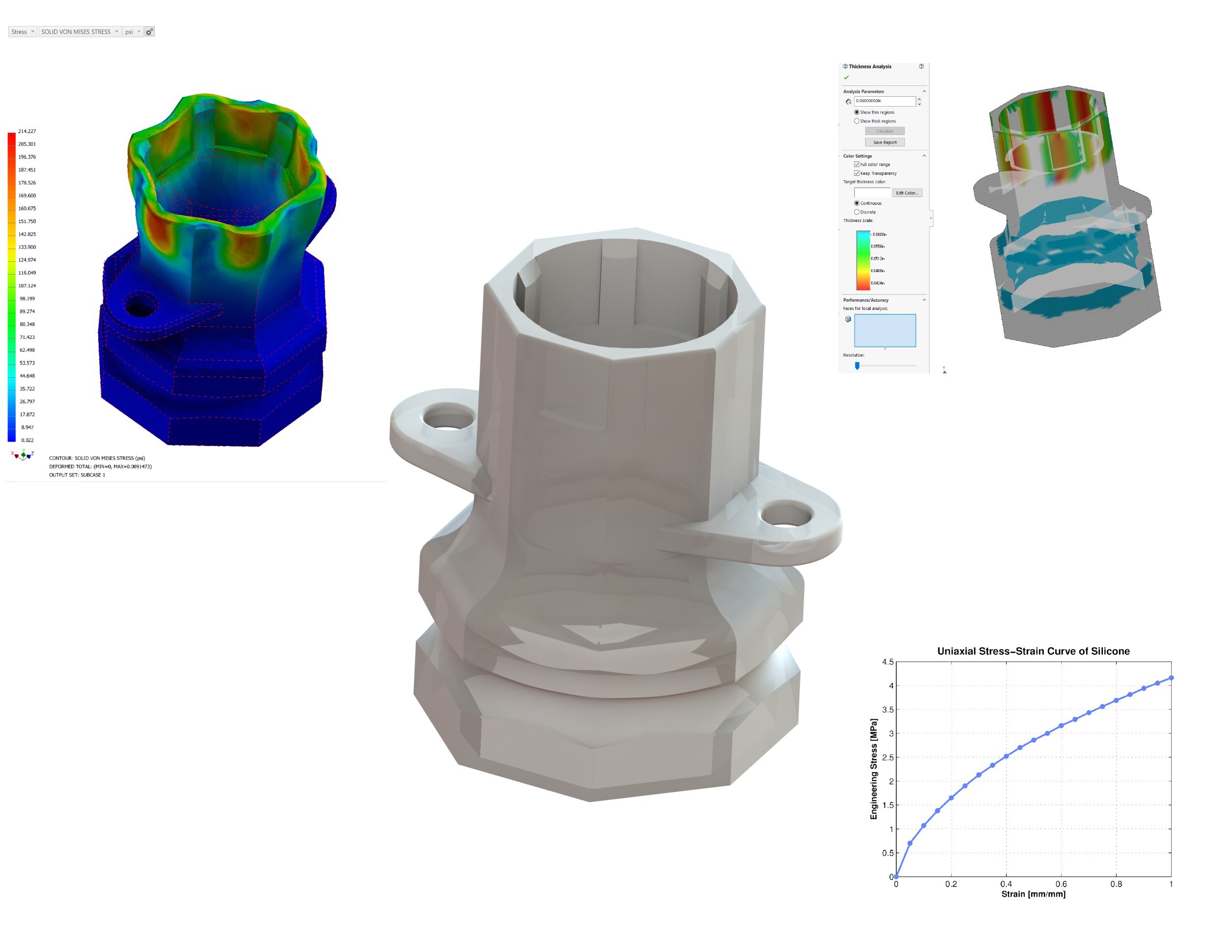
Fig. 2: Here, the gasket design seen in Fig. 1 is modeled using plastic flow simulation and finite element analysis (FEA) software which helps to optimize injection molding by assessing material flow, gating and other factors in the molding process.
Therein lie the greatest strengths of Injection-molded prototyping: it allows for functional testing (e.g., mold flow assessments and scalability conversations) to begin earlier in the development process by creating a true-to-production, high-quality part. A molded prototype allows the manufacturer to debug potential manufacturing issues — modeling how the part will fill the tool (i.e., flow and gating), whether it will stick/eject, any potential issues as far as warpage, etc. — and to alter the tooling or tooling methods to alleviate those issues before production-scale tools are built (Fig. 2).
Manufacturing difficulties that simulation does not predict almost always arise; they are not discovered until a production tool is used. This can be problematic when working with 3D printing organizations that are happy to accept a design and print it using the customer’s choice (from among their selection) of materials, but normally provide little to no feedback regarding the part’s future manufacturability.
Caplugs has invested in the capability to produce both high-quality, 3D-printed prototypes and single-mold prototypes to overcome this hurdle. As experienced injection molders, we can take design considerations into account for production moldability. In short, we would not 3D print a part prototype we know is not manufacturable (i.e., at large scale, using injection molding).
Jeff Exley is Director of Engineering at Caplugs with over 20 years of experience in plastics engineering and product management, working with customers across a wide range of industries, A graduate of the plastics engineering program at Penn State Behrend, Exley can be contacted at jeff.exley@caplugs.com.
Craig Brown is Vice President of Engineering and Tooling at Caplugs. Brown graduated from Penn State with a degree in chemical engineering, and has worked in the plastics industry for 25 years, particularly in operations and engineering management for injection molding operations. He can be reached by emailing craig.brown@caplugs.com.
Caplugs has been a leader in plastic molding since 1948. Built to cater to our customers’ plastic and silicone component needs, Caplugs boasts six different manufacturing processes to offer a variety of solutions as a long-term partner for a wide range of projects. Today, Caplugs has 16 facilities across the globe – including three dedicated to medical molding. Customers can choose from 40,000+ catalog parts that are in stock or work with our dedicated and experienced team of product engineers to design a custom part, from concept and prototyping through design-for-manufacturability (DFM) review, recommendations and full production. Caplugs also builds and maintains tools in house, ensuring quality, consistency and efficiency.